The Shape of All Possible Orientations
A 3D printer asks one question before anything else — which way up? — and the answer lives on a sphere with a circle hidden over every point
Stand a part on a printer’s bed one way and it prints clean. Turn it over and half its surface hangs in mid-air, needing scaffolding that you will later snap off and throw away. Choosing between those outcomes is a search, and the first question is what you are searching over. An orientation takes three numbers, but only two of them change anything: spinning the part on the bed like a turntable leaves every overhang exactly as it was. So the search happens on a sphere. The third number has not gone away, though — it is still there, a circle of ignored choices sitting over every point of that sphere, and the way those circles fit together is one of the most celebrated objects in topology.
1. Which way up?
A fused-filament printer builds a part in horizontal layers, from the bed upwards. Each new layer needs something beneath it to rest on. Where the surface leans out too far — the usual rule of thumb is more than 45° from vertical — there is nothing underneath, and the slicer has to print a disposable lattice to hold the material up until it sets. That scaffolding costs filament, costs time, leaves scars on the surface it touched, and has to be removed by hand.
Which faces overhang depends entirely on how the part is standing. Here is a small bracket, printed two ways. Every face is coloured by whether it needs support.
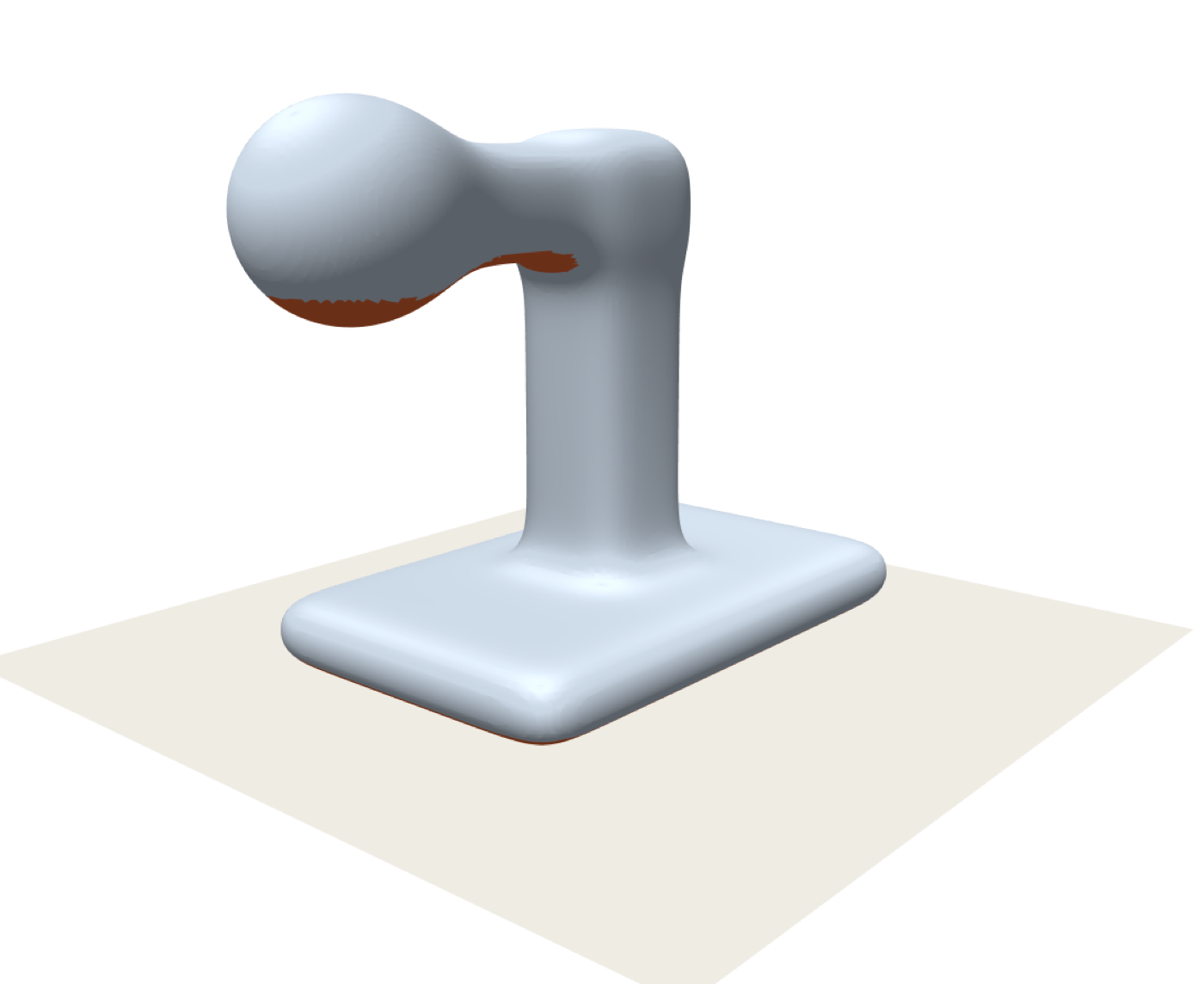
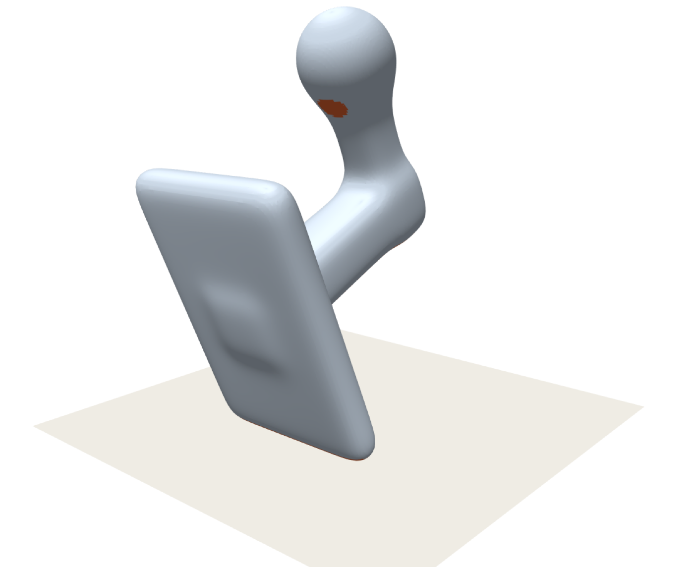
So: find the orientation that minimises the clay. That sounds like a search over the rotation group — three degrees of freedom, whichever way you like to coordinatise them. But it isn’t, quite, and seeing why is the whole point of what follows.
2. The number that does nothing
Take the good orientation from Figure 1 and, without tipping the part at all, rotate it about the printer’s vertical axis. Spin it on the bed like a cake on a turntable. Watch the clay.
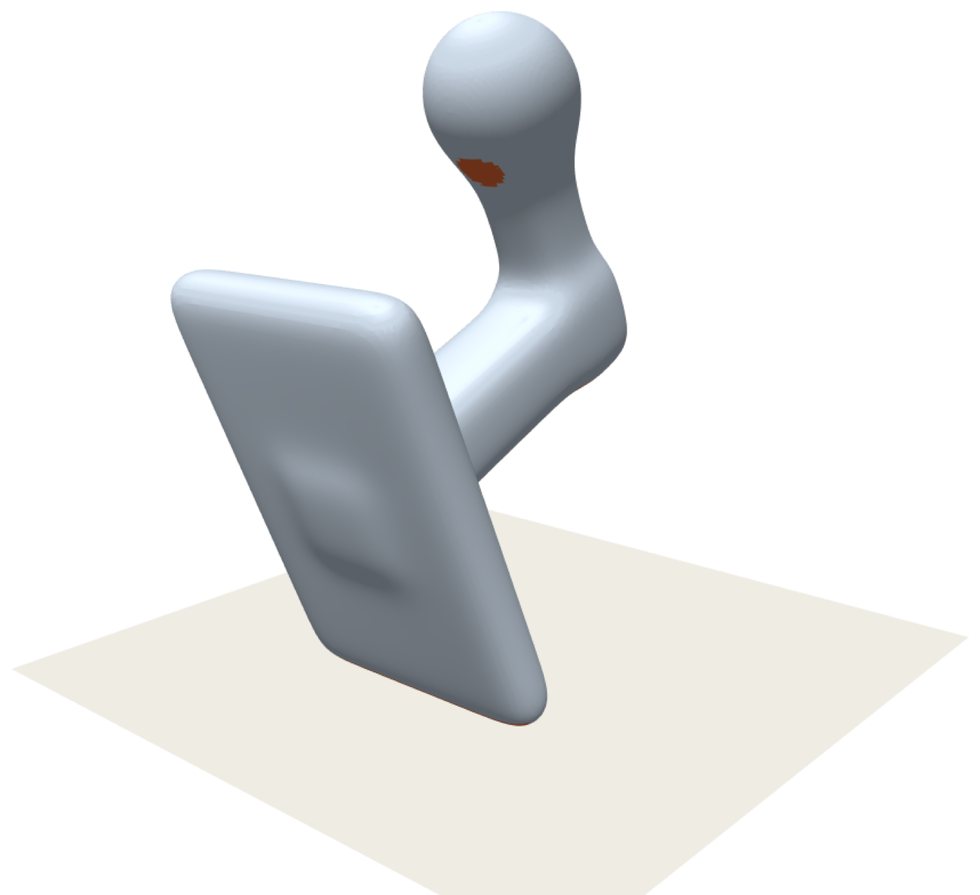
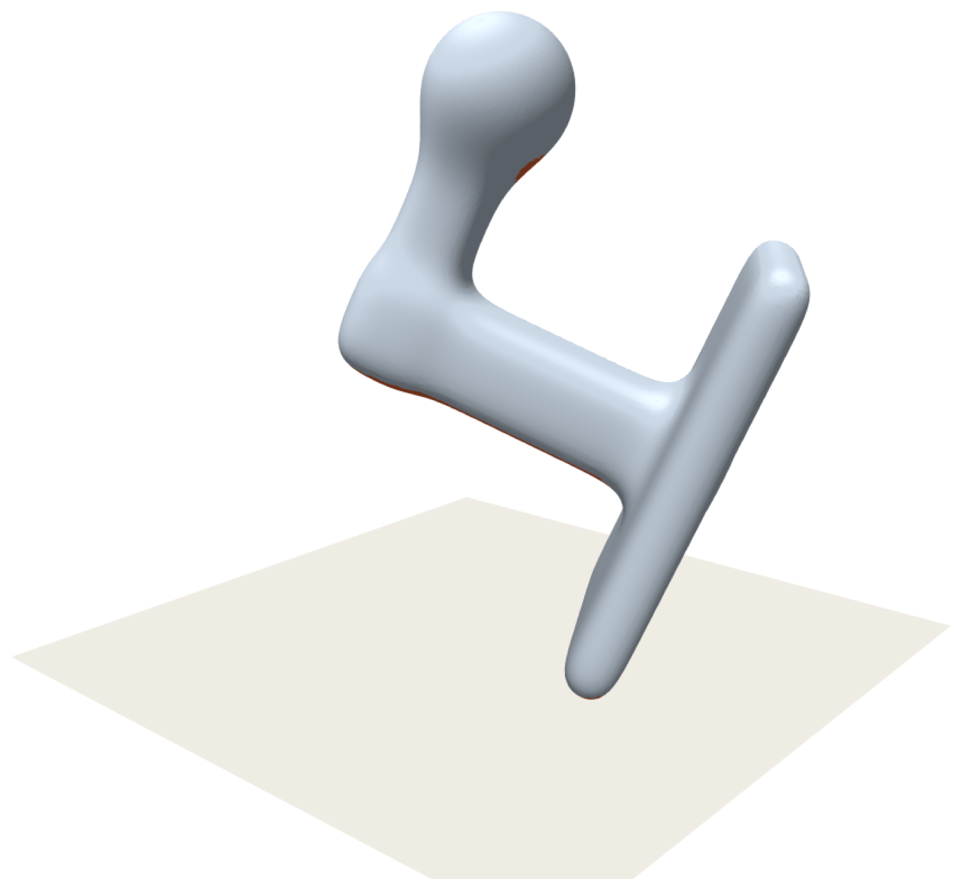
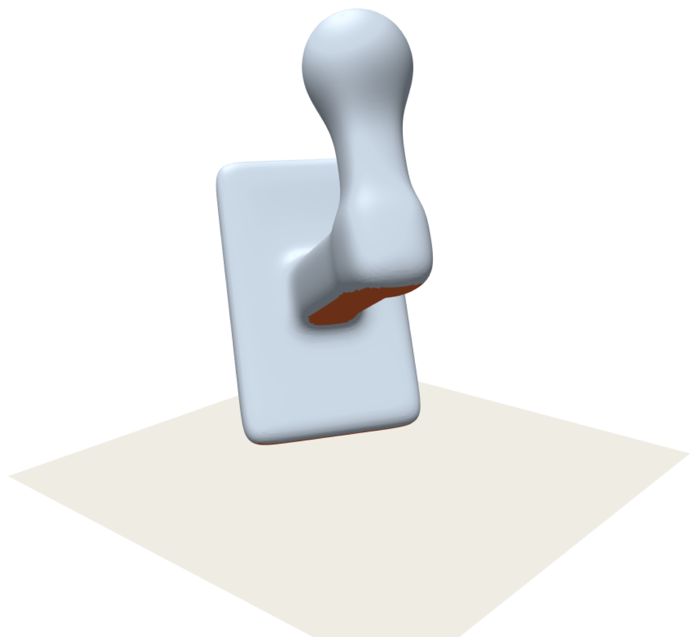
The reason is a one-line calculation. Whether a face overhangs depends on the angle between its normal and straight up. Rotating the part about the vertical axis rotates every normal about that same axis, and a rotation about the vertical preserves the angle everything makes with the vertical. The support cost cannot possibly notice.
What the cost does notice is one thing only: which direction of the part ended up pointing at the ceiling. Call that the build direction. It is a unit vector, drawn in the part’s own frame — a point on a sphere. Every orientation determines one, and any two orientations with the same build direction cost the same to print.
3. The landscape you are actually searching
If the cost depends only on the build direction, then the search space is the sphere of directions, and the cost is a function on that sphere. We can simply draw it: for every direction, tip the part that way and measure the area that would need support.
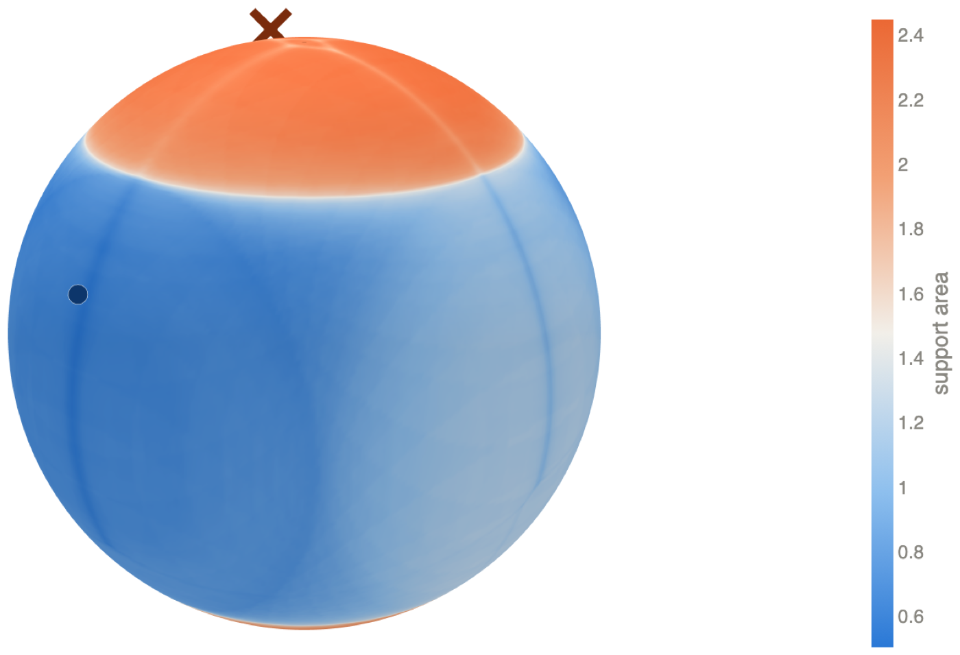
The cost here counts overhang area and nothing else, which is why the winner in Figure 1 happily balances the part on a narrow face. A production slicer weighs several terms at once — how firmly the part grips the bed, how tall the print ends up, which surfaces the support will scar — and the optimum shifts accordingly. That changes the landscape on the sphere; it does not change the fact that the landscape lives on the sphere, because every one of those terms is equally blind to the turntable.
This is a genuinely two-dimensional search, and a small one. A few thousand directions cover the sphere finely enough to find the optimum. Had we insisted on searching orientations proper, we would have been sweeping a three-dimensional space and evaluating the same answer over and over — once for every turntable setting of every direction.
4. Where the third number went
Discarding the spin was the right thing to do, but it is worth asking what exactly was discarded. Fix a build direction. The orientations that realise it are not unique: there is a full circle of them, one for each turntable angle. Fix a different direction, and there is another circle. The space of all orientations is therefore assembled out of circles — one circle sitting over each point of the sphere — and the sphere is what you get by collapsing each circle to a point.
It is tempting to conclude that the space of orientations is just “a sphere times a circle”: pick a direction, then pick an angle. It is not, and the obstruction is one you have already met. To write an orientation as a (direction, angle) pair, you must first decide, for each direction on the sphere, which turntable setting counts as angle zero. That means choosing a reference direction tangent to the sphere at every point, varying continuously — combing the sphere flat. The hairy ball theorem says you cannot. Somewhere the comb must part, and that is exactly where naive angle coordinates go wrong.
So the circles are stacked over the sphere in a way that is locally a product and globally twisted. Written out, with \(S^1\) the circle, \(S^3\) the space of orientations and \(S^2\) the sphere of build directions:
\[ S^1 \;\longrightarrow\; S^3 \;\longrightarrow\; S^2 . \]This is the Hopf fibration, found by Heinz Hopf in 1931. The middle space is the 3-sphere — the unit quaternions, which is how orientations are almost always stored in practice — and the map to \(S^2\) is nothing more exotic than “given this orientation, which way is up?”
5. What the circles look like
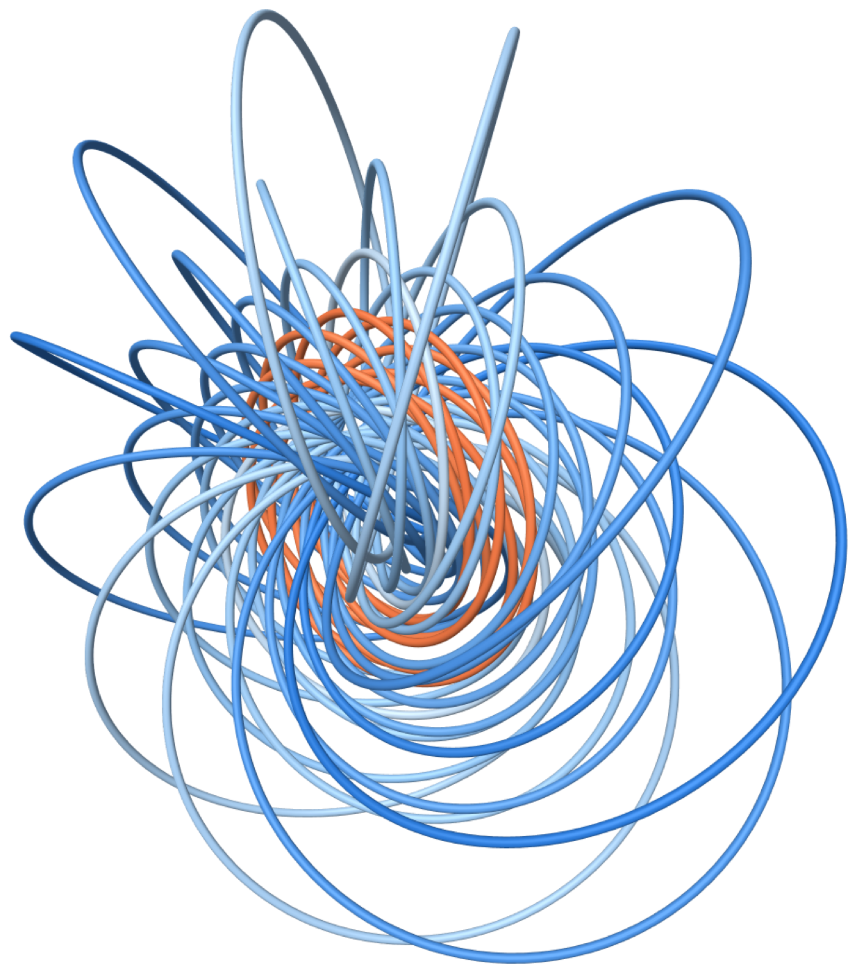
The 3-sphere does not fit in our space, so to see the circles we do what cartographers do: project. Stereographic projection maps the 3-sphere, minus a single point, onto ordinary three-dimensional space. It distorts sizes — a circle passing near the missing point comes out enormous — but it is faithful about what matters here: circles stay circles, and curves that are linked stay linked.
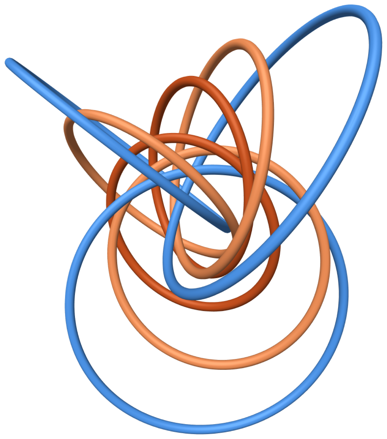
That every pair is linked is not a quirk of the drawing. It is measurable: computing the Gauss linking integral for any two of these curves returns 1, and that number is what makes the fibration twisted rather than a plain product. A product \(S^2 \times S^1\) would have disjoint, unlinked circles that you could pull apart like beads on separate strings.
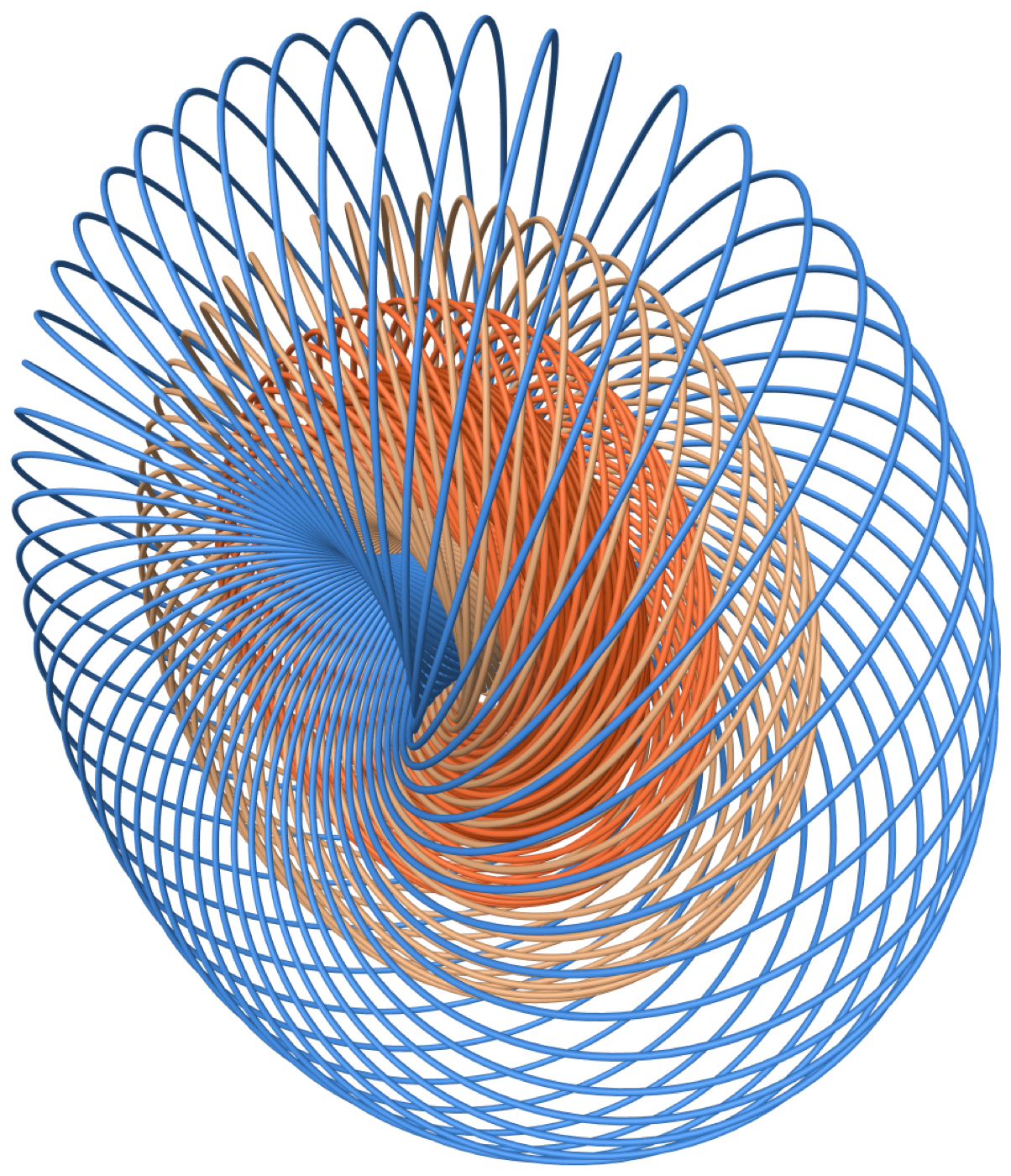
Take not eight directions but a whole circle of them — all the directions tilted, say, 74° from the part’s own axis — and their circles sweep out a torus. Take several such rings and the tori nest inside one another, filling the space.
6. The landscape, lifted
Figure 3 and Figure 5 are two views of the same thing, and it is worth putting them side by side. Colour each circle not by its latitude but by what that build direction costs to print, and the cost landscape from the sphere reappears upstairs.
7. Why this earns its keep
None of this changes the answer for our bracket — a fine enough grid on the sphere finds the optimum whether or not you know what a fibration is. Where the structure pays is in knowing how to build the grid, and there the naive choice is wrong in a way that is easy to miss.
The obvious way to sample directions is to pick the two angles that describe them — how far from the pole, how far around — and draw both uniformly. It does not work, for the reason every map of the world makes Greenland look enormous: equal steps in the polar angle do not cover equal areas. The fix is to sample the cosine of the polar angle uniformly instead, which makes area, not angle, the thing spread evenly.
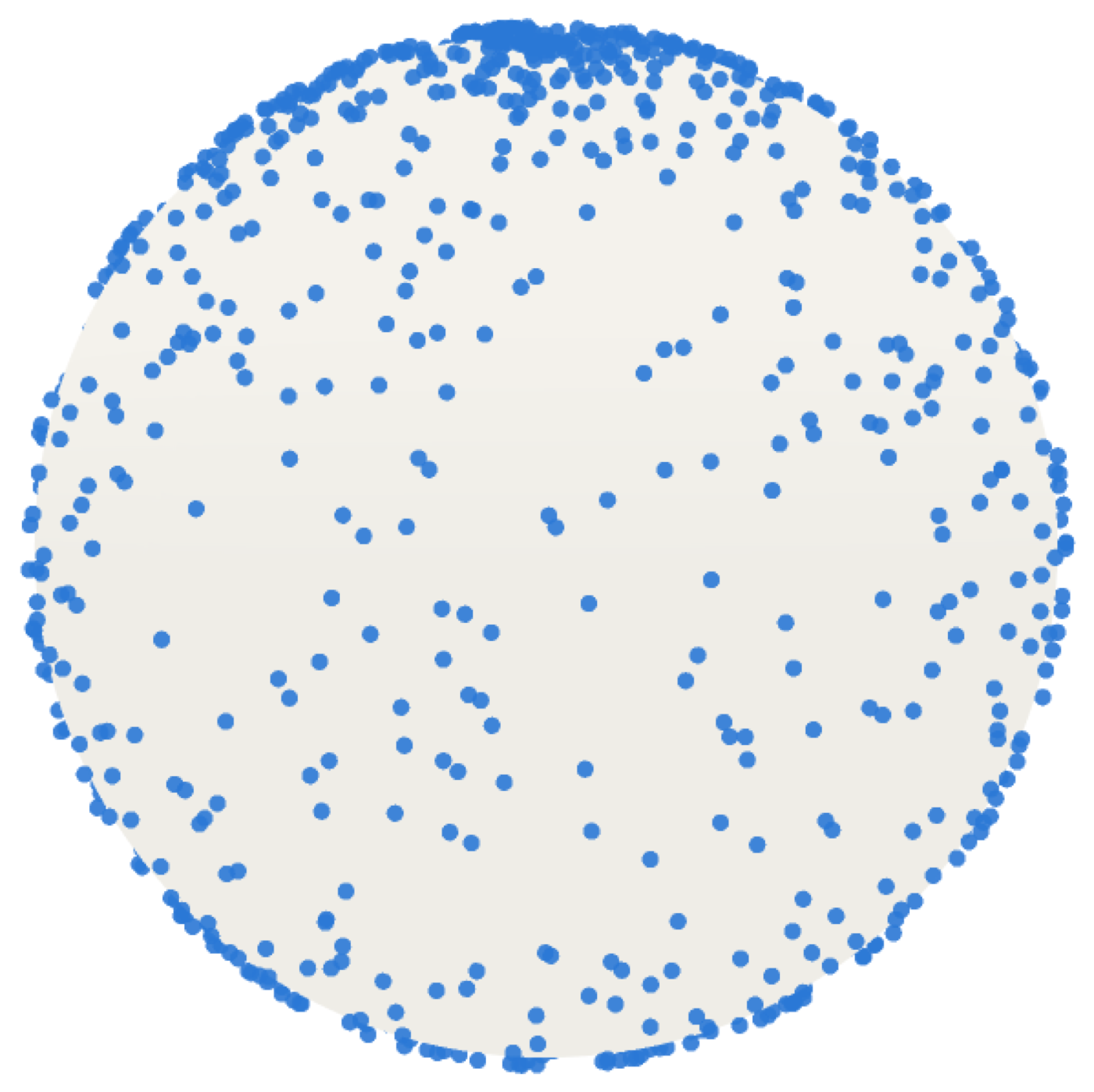
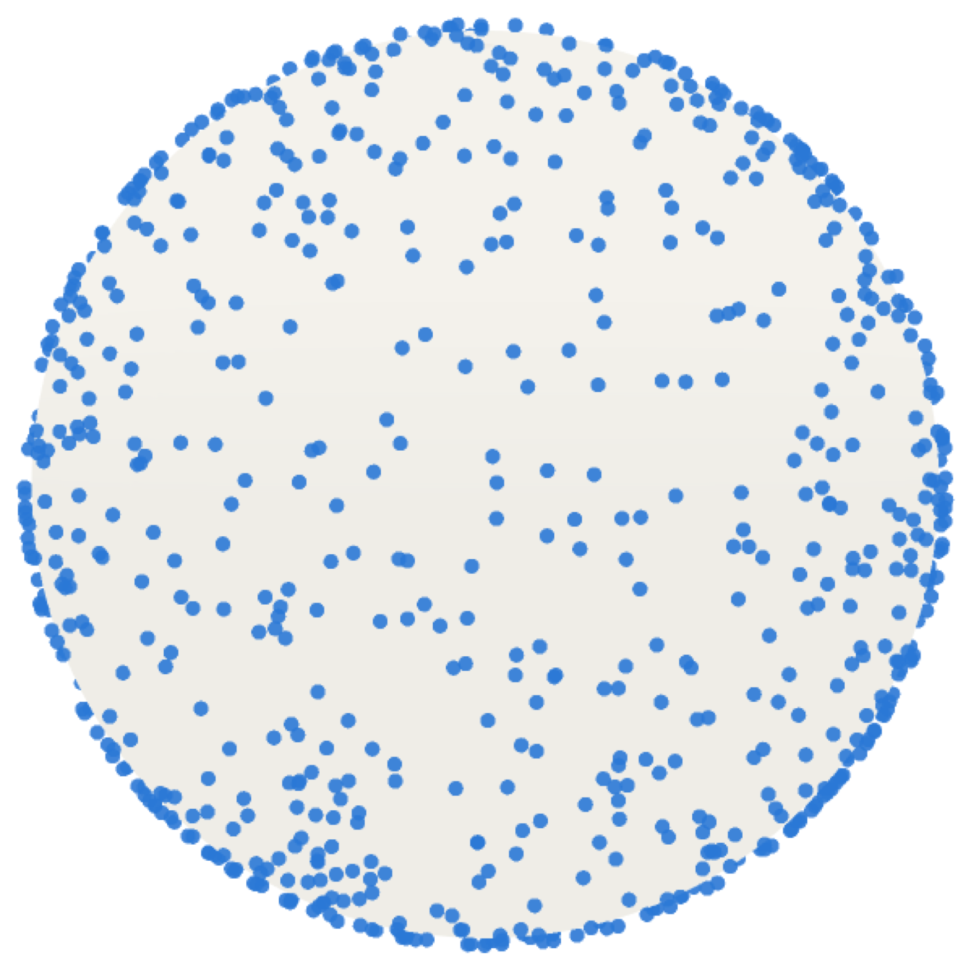
This matters beyond our problem. Plenty of orientation searches genuinely need all three numbers — packing several parts on a plate, planning a robot’s wrist, matching a molecule against a density map — and for those you want a grid on the full space of orientations that is uniform and that can be refined without starting over. The best known construction does exactly what this article has been describing, in reverse: take a good area-uniform grid on the sphere of directions, take a good sequence on the circle, and assemble them through the Hopf map. Yershova, Jain, LaValle and Mitchell set this out in 2010, and it remains the standard recipe. The fibration is not decoration on that construction; it is the reason the pieces fit together without seams or clumps.
8. Try it
The whole argument of Section 2 — the claim that the third number does nothing — is four lines to check. Mesh the part, take the outward normal and area of every triangle, and add up the area that overhangs:
def support_area(normals, areas, centroids, verts, d, angle=45):
    """Area needing support when direction d of the part points up."""
    steep    = normals @ d < -np.cos(np.radians(angle))
    on_plate = centroids @ d - (verts @ d).min() < 0.02   # the bed holds these
    return areas[steep & ~on_plate].sum()
Notice what the function is handed: a direction, not an orientation. There is nowhere to put a turntable angle, because there is nothing for it to do. Feed it any orientation you like, extract the build direction, and every one of the infinitely many orientations sharing that direction returns the identical number — which is what the accompanying test suite checks, to the last bit, along with the claims that the fibres are round circles, that distinct fibres never meet, and that any two of them link exactly once.
There is a moral here about modelling, and it is not really about printing. Before searching a space, it is worth asking which of its directions your objective can actually feel. The answers often factor: the thing you care about lives on a smaller space, and what you are quotienting out has a shape of its own. Sometimes that shape is dull. Once in a while it is a circle bundle over a sphere that Heinz Hopf found in 1931, and the pictures are worth the detour.
Further reading
- H. Hopf, Über die Abbildungen der dreidimensionalen Sphäre auf die Kugelfläche, Mathematische Annalen 104 (1931) — the original.
- A. Yershova, S. Jain, S. LaValle and J. Mitchell, Generating uniform incremental grids on SO(3) using the Hopf fibration, International Journal of Robotics Research 29 (2010) — the sampling construction of Section 7.
- N. Johnson, Visualizing the Hopf fibration — an animated treatment, if you would like to see Figure 5 turn.
I work as an independent consultant helping engineering and computational teams solve difficult problems in geometric modeling, surface processing, and algorithmic design. If your team is tackling a non-trivial spatial or mathematical challenge, reach out directly at cvalero@carlosvalero.com.